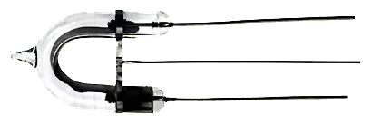
UB1221 - U-Flash Tube 4WS 60Z/min
Product no.: UB1221
Features:
• Xenon filled quartz glass tube with pressed in electrodes
• For triggering, a metal wire is attached to an electrode which transmits trigger impulses.
• RoHS compliant
| Technical Specifications |
| Part Nr. | URated | Umin. | Us | E | Z | L | UT | ET |
| [V] | [V] | [V] | [Ws] | [kV] | [mW] | |||
| UB1 | 300 | 200 | 400 | 60 | 6 | 1x10⁴ | 6 | 0,8 |
| UB1221 | 300 | 200 | 400 | 4 | 60 | 1x10⁶ | 4 | 0,6 |
| UB6531 | 300 | 250 | 400 | 60 | 6 | 1x10⁴ | 6 | 0,8 |
| UB0661 | 350 | 270 | 500 | 8 | 60 | 2x10⁶ | 4 | 0,6 |
| FT218 | 450 | 350 | 500 | 250 | 4 | 1x10⁴ | 6 | 0,8 |
| URated = Rated Voltage, Umin. = Minimum Voltage, US = Peak Voltage, Z = Discharging/Minute (Max.), L = Operating Expectancy (Total No. of Discharges), UT = Trigger Voltage, ET = Primary Performance of Trigger Coil | ||||||||
| Dimensions |
| Part Nr. | e | d | a | c |
| [mm] | [mm] | [mm] | [mm] | |
| UB1 | 32 | 6 | 16 | 15 |
| UB1221 | 29 | 6 | 19 | 40 |
| UB6531 | 38 | 6 | 13,5 | 40 |
| UB0661 | 40 | 6 | 13,5 | 40 |
| FT218 | 55 | 8 | 25 | 40 |
Operating / Function: To operate the xenon flash tubes, a circuit in accordance with the below-mentioned circuit diagram is recommended. The operating method of this circuit is as follows: 1. The capacitor CS, parallel to the xenon flashtubes F. T. (see circuit diagram) is loaded through the voltage source V. 2. The capacitor CT is charged through the voltage divider (R1 and R2). 3. Primary winding of the trigger coil Tr and the circuit S are switched parallel to the capacitor CT. Secondary winding of the trigger coil is connected to the trigger electrode of the xenon flashtube. 4. When the circuit S is closed, the capacitor CT discharges through the trigger coil and a high voltage impulse leads to triggering of the flashtubes. The energy stored in the capacitor CS discharges by reducing the internal resistance of the gas discharge tubes. The choke L provided in the circuit is only required if CS is an MP capacitor.
| Note |
| Trigger coils suitable for all flashtubes are available. |
| Flashtubes | Trigger Coil |
| UB1 | ZTR 200 |
| U1221 | ZTR 200 |
| UB6531 | ZTR 200 (4 kV) oder ZTR 32 (6 kV) |
| U0661 | ZTR 32 |
| FT218 | ZTR 32 |
circuit diagram:

